


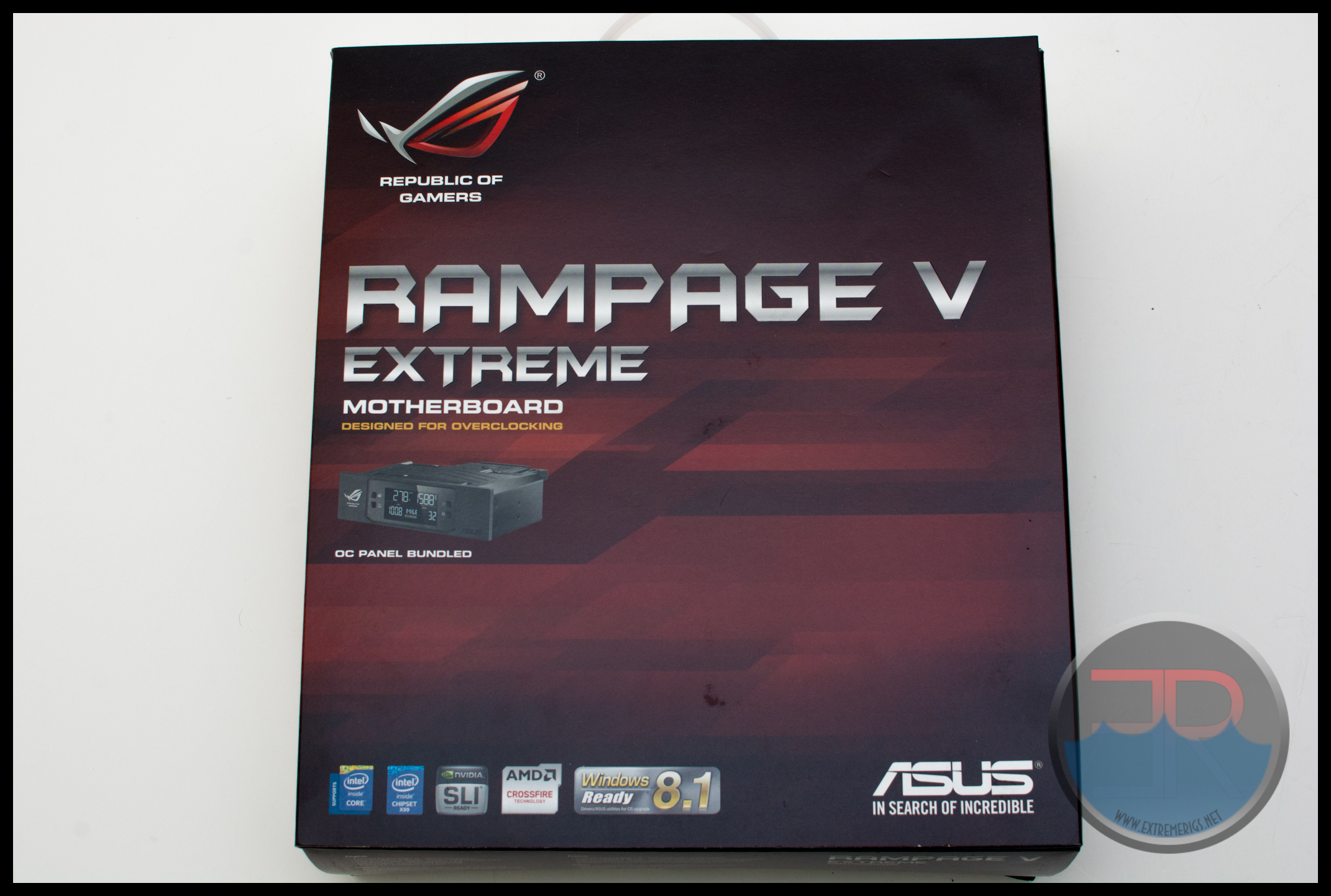
The Rampage V Extreme box is consistent with ROG’s recent style, in fact it looks pretty much identical to my other ROG boxes since the R3E launched 5 years ago:
Like the other ROG boxes you get a window to make sure of the motherboard layout and that nothing is damaged/used before you buy:
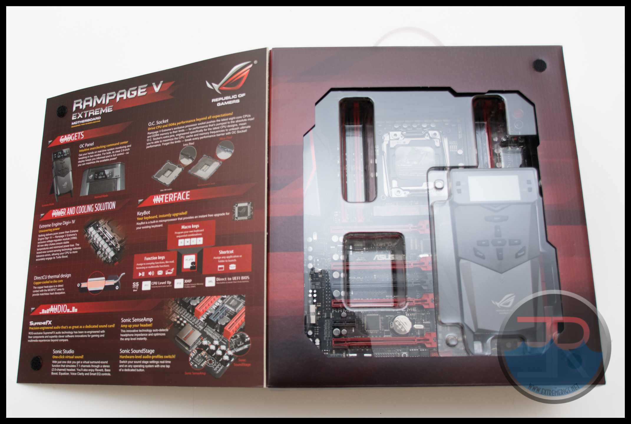
The flap also shows you some marketing info on what makes the R5E so special, as does the back of the box:
 The O.C. Socket is one of Asus’s unique highlights on the X99 motherboard generation. Specifically made for overclocking this sockets includes more pins that touch pads on the CPU that the default socket doesn’t. Asus have a good write up on that here. We’ll talk more about it later too!
Inside the box are two more boxes – one contains all the accesories while the other contains the motherboard itself and the OC Panel.

The plastic quickly lifts off showing you the motherboard itself:

The immediate thing I noticed the first time I saw a R5E motherboard was that they finally got rid of all the white plastic parts on the PCIE and DIMM slot levers. We’re left with a much cleaner look now.
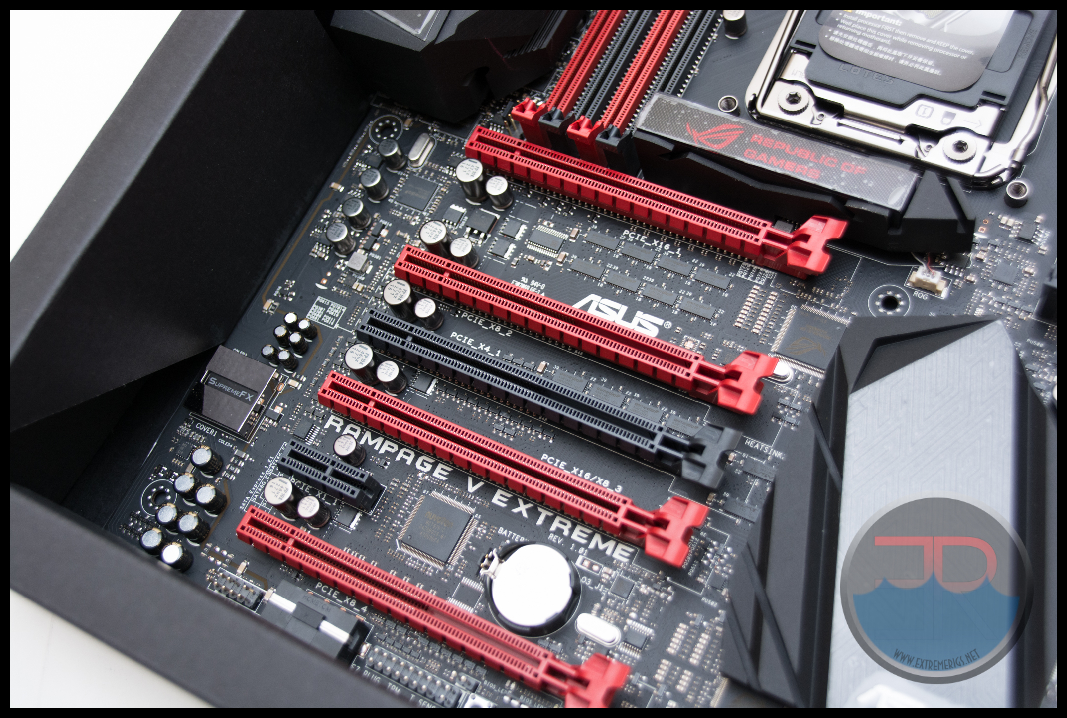
The heatsinks are also a step up from the R4E which was a tad ugly and boring.

Like the black edition of the Rampage IV – the VRM heatsink uses a heatpipe to connect to secondary heatsink that also acts as a cover for the normally ugly IO.
 We can see a fat stack of USB3s here – possibly the most I’ve ever seen. AC WiFi is also included this time, again like the black edition. I love that there is still a legacy PS2. Although I almost never use a 2nd LAN port it’s the one thing apart from a thunderbolt connector that is really missing here.
 The southbridge this time around is disconnected from the VRM air cooler. We like this – because the south bridge doesn’t get that hot, some users buy a water block only for their VRM and being able to keep the stock block on the board is nice. It’s also nice that Asus got rid of the annoying south bridge fan that was unnecessary on the R4E.

This heatsink lights up with an LED underneath the plastic sectuib. It’s also worth noting here just how smooth the PCB is around the socket. It has a very high quality matte black feel to it.

The area around the CPU is relatively clear which is helpful for the sub-zero LN2 crowd wanting to insulate this area. For CPU power there is a 8 pin and a 4 pin connector. I’m still surprised ROG haven’t moved back to 8+8 pin considering this is designed for LN2 benching and the 5960x is a beast power wise. For “normal” overclocking though this is plenty.

The VRM heatsink is chunky and fits the ROG theme – however it doesn’t have a lot of surface area so we will have to check the VRM temperatures under load later on! Presumably the heatpipe that connects it to the IO cover/heatsink helps though:
 In the top corner we see a lot of the “user interface” that you will be playing with if you are benching. :
 From the left starting next to the 24 pin connector:
– Top (black switch) – “Mem OK!” Button
– Bottom (white switch) – “Retry” Button
– Red Switch – “Safe Boot” Switch
– On/Off Switch – “Slow_Mode” – This turns down the processor speed down to enable an easier way of overcoming difficult load/temperature transitions during LN2 benching
– Black Reset Switch – hardware reset – a copy of the reset you’d be used to on the front of the case. Absolutely necessary for a bench setup and useful for everyone else too.
– Black Jumper above the Black Reset Switch – LN2 Mode – motherboard goes into a special mode to fix and “cold boot” issues
– Red “Start” Switch – hardware power switch – a copy of the power switch you’d be used to on the front of the case. Absolutely necessary for a bench setup and useful for everyone else too.
– Top – 4 Way Dip Switch – Turns on/off individual PCIE lanes, very useful for debugging multi way GPU issues without pulling the cards (e.g. when water blocked or setup for LN2)
– Bottom – 2 Digit “Q” code – this is one of the most useful debug items on the entire board – the 2 digit code can be referenced with the manual and gives an indication of where the motherboard has “got stuck” or what mode it’s in. Essential for anyone. One thing I liked about the X79 dark was that after boot it defaulted to measuring CPU temperatures. The R5E default is to show AA which is indicated it’s safely transitioned into it’s ACPI power management mode after boot.

To the left of the 24 pin connector is a red USB3 header. Above it is a M.2 SSD connector which can handle three different standard sizes up to 110mm in length. Although I initially loved the idea of M.2 for mITX rigs, it’s great for full size boards too. These days more and more enthusiasts are simply running one large SSD and not having to hook up a sata cable (of any type) as well as power means a cleaner look! There are two more fan headers above the 24 pin, while under it are four LEDs and 9 probe points. The four LEDs are debug LEDs that light up during boot to show which stage of initialization the motherboard is at. They also stay lit up red if there is a problem with each of the areas – CPU, DRAM, VGA and Boot Device. These can be really handy particularly if you’ve done something stupid like forget to add power to your VGA card. Bear in mind these are not exact. They are another debugging tool to use but only indicate where the problem may be. For example I’ve had dead motherboard VRMs misleadingly point to the GPU before.
 At the bottom of the board we have a ton of headers. These may be blocked or hard to access if you are running quad GPUs. Starting at the bottom right:
Bios Switch (Red) – switches between the two bioses – there is an indicator LED further over to the left by the PCIE slot which is next to the socketed BIOS chips themselves.
Above – “KeyBot” switch – Keybot is a cool idea it basically intercepts key presses from a keyboard on a designated PCI port and enables macro functionality. In other words even if you don’t have a macro keyboard – now you can enable it in hardware! This is awesome and also adds more functionality even to Asus’s own macro keyboards such as the Strix which we reviewed. The strix has dedicated macro keys but the hardware only lets you set macros to the dedicated keys and not to any key. KeyBot allows you to make any key a macro key!
To the left of the Bios Switch – “Front Panel Header” – this contains all the LEDs and power/reset switch connections. ROG are also nice enough to give you a “header” to attach to this so that it’s easier to connect and disconnect.
Black Connector (above the front panel header) – this is the connector for an addon thunderbolt daughtercard. Unusually this daughtercard is not included in the package. It’s surprising that the OC panel is included but you have to pay extra for thunderbolt which could have been put on the IO panel instead.
Next to the thunderbolt port are two 2×4 pin header connectors, a 2×2 header, a 1×4 header and a 1×3 header. These are ignored by the manual and only the 2×2 seems to be marked for sata clocks. We suspect these are all debug ports for the engineers and not meant for us mere mortals.
Left of the front panel header is a 2×4 and a 2×4.5 header all marked as “ROG-EXT” – this is the header used to connect the OC Panel. The 9 pin header is a standard USB so if you’re not using the OC Panel then you can repurpose this if needed.
“USB1314” – Not surprisingly another USB header. This means two total USB2 headers and 2 USB3 headers
CHA_FAN2A/B – 4 pin fan headers – like the rest of the fan headers (7 total) they can be controlled by voltage or PWM signal (assuming compatible fans) and automatic profiles can be created in the bios or through Asus’s software.
Moving further to the left now:

From right to left again:
USB3 Header in red
Two socketed bios chips
“Soundstage” Button – this is a bit of a strange one – it lets you switch audio profiles set in hardware by pushing the button. However for most gamers this won’t be easily accessible. This really should be on the OC panel menus when mounted in a drive bay.
2 Pin header – Thermal Sensor 1 – there are three of these scattered around the board that can be hooked up to the included thermal probes.
“TPM” Header – this is a header to connect to an optional security dongle, most people won’t be using this!
4 Pin Molex – Some power hungry GPUs can require extra power from the motherboard, and when running 3-4 GPUs this can overload the motherboard power from the 24 pin connector leading to dangerous burnout. This molex is used to deliver auxillary power to the PCI slots. This has been around since the Rampage III and was improved to a 6 pin pci connector on the Rampage IV. Sadly we’ve gone backwards to the R3E design here. Molexes are large, ugly, awkward and this is rotated so that some cases will not be compatible anyway. The 6 pin connector had 3x12V lines and 3 Grounds, while the molex only has 1 12V wire and 2 grounds. This is worse on so many levels.
“AAFP” header – this is the front panel audio connector for headphone/mic etc
 Taking a look at the back of the board then we see some interesting things. There avery only a few components exposed here which is a good thing. Then there are some additional pieces of metal. The most obvious is the backplate for the CPU socket. The VRMs also get a backplate and so does the south bridge. The latter is unusual as thermally it shouldn’t be doing anything (unlike the VRMs) and it seems unnecessary to get a lot pressure on the south bridge either:
 It’s also raised quite far off the board:
 On the Rampage IV Extreme – cooling of the VRM “underplate” was necessary for maintaining a high overclock at high power loads continuously:
 We will be testing to see if throttling still occurs without active cooling of this plate.
In the middle of the back of the board is a table showing which PCI lanes are optimal based on which CPU you have:
 In other words with a 5820K you can run 3 GPUs with PCIEv3x8 on each card which should be plenty. The back of the board also features the LEDs that provide the red glowing strip:

The strip itself is just regular PCB – but the usual metal power planes and signals have been cut so as to isolate this one section for improved signal to noise isolation on the analog secton. The fringe benefit is that the light shines through the PCB for a cool effect:
 The audio is no slouch either courtesy of the Supreme FX chipset:
 Motherboard audio has improved a lot now, and to do much better it would be wise to move to an external USB DAC in order to further isolate system level noise from the analog components.
Lastly let’s take a look at the modified 2011-3 socket:
 Hopefully you didn’t take the time to count the pins. Functionally the socket works as you expect, and the screw and mount points are compatible:
It’s unclear exactly how Asus are using the extra pins – their marketing slides show that it prevents voltage droop on VCCIN but it’s not clear if this is by providing less resistance through more contacts or if some are used to sense the droop and provide better LLC to the VRMs. X99 is different to X79 in that the VRMs only provide VCCIN to the CPU, which then has internal regulators to generate the “other” internal voltages. This means higher power to dissipate on CPU because of inefficiencies in these internal regulators, but also that you no longer get to have a premium regulator design for those voltages on your motherboard. In other words Asus’s VRM design matters less than it used to because the droop will be somewhat regulated out by the internal CPU regulators. If the CPU has a good internal regulator with perfect power supply rejection then it will be tolerant of some amount of droop on VCCIN. However having the best most stable VCCIN will always give the CPU regulators the best chance to provide a perfect supply to the CPU’s circuits. This is similar to having a good power supply where droop insensitivity is a good thing, but rarely does it significantly change an overclock unless you are benching. So if this sounds like I’m saying that the R5E is overkill for most watercooling type overclocks then that’s correct. However that was always going to be the case because it was designed with subzero overclocking in mind. The best analogy I can think of is that this is like a BMW M3 – it’s designed to handle racing, however the majority of M3’s have never even see a race track. In other words they have a ton of margin in design for what most people use them for e.g. driving aggressively on the street. The same is true for the R5E – even if you don’t bench it means that you have a board that can handle a 24/7 overclock on water with a ton of margin.

I’m a fan of overkill so this is right up my street. Let’s now rip off those heatsinks and see what’s actually underneath!


The Ultra has not dissapeared, see Asus Z10 D8 WS + E5-2699v3, it’s called Workstation.
Agreed, I was referring to systems that could overclock While “real” workstation users will use that workstation board happily my “idea” of ultra enthusiasts consist of people who won’t give up their overclocked performance but still want more cores and are willing to pay for 2P. Those same workstation users who prefer more cores might even be happy with a 4P after all. Since the SR2 there have been no real overclockable 2P chips.
[…] Asus Republic of Gamers Rampage V Extreme X99 Motherboard Review for Overclockers! […]
Nice Review! Helped me a lot!
Can you tell me the name of the Waterblock in the top picture please? It looks so sick!
MIPS IceForce HF – MIPS closed down and I think AquaTuning bought all the remaining stock – so that might be your best for these if any remain!
Thank you very much!
[…] Asus Republic of Gamers Rampage V Extreme X99 Motherboard Review for Overclockers! […]
I think this board is too much oriented to the LN2 and TEC peoples. Of course we live under their umbrella so if ASUS covers those peoples, we are covered too. But sadly, most of us mortals won’t even use these hardware level (and few software level) features for WC builds, so don’t you think there should be lower-dog of ROG (probably R5 Formula) for X99? Or does Deluxe suffices?
I have to admit I’d rather see a Gene matx version before a formula. Yes for some the deluxe suffices for that role though
[…] Asus Republic of Gamers Rampage V Extreme X99 Motherboard Review for Overclockers! […]
Comments are closed.