MPS 400 Internals
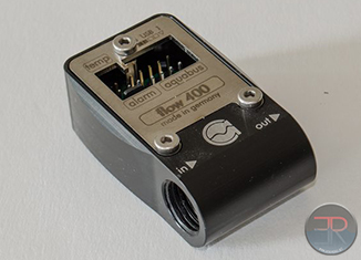
The MPS400 flow sensor is so small that it simply can’t house a lot of stuff. Therefore it was expected that it would contain some sensor that would integrate with a microcontroller and presumably that microcontroller would handle the USB and aquabus links and any ADC functions for the flow sensor and the temperature sensors. Taking off the front plate then we were not too surprised:
Connectors and the mystery sensor hidden under a sticker. Once the sticker was removed then the sensor could be seen better:
It’s a freescale part and you can see the datasheet here. You can just make out the two tiny barbs that push into the plastic housing that have a rubber seal around them. The nice thing is that the sensor is internally temperature compensated already. It is also supposed to give a linear output of pressure. Pressure of course is relative to velocity squared so the curve outputted by the DAC does indeed look like a square root function. Presumably the microcontroller is on the back of the PCB. I didn’t check because it’s of little interest.
So the MPS promises a lot and comes in a very small package but how does it perform?






[…] sensors will be compatible – only the pulse style that is most common. Not the fancy new AquaComputer […]
How would you recommend calibrating this sensor suite (flow, temps) in a system? Any specific tool? Should it be re-calibrated once in a while?
I just found out that my multimeter has a type k thermal probe (no idea what that means, though). Is that enough to calibrate the internal thermal sensor of the mps?
Hah well thermal probes themselves often need to be calibrated. Since that review was written AquaComputer fixed the bug with the non linearity, so it should be a lot better now. Unless you’re really testing stuff it’s probably good enough to be honest. If it’s not it’s probably easier to buy a 10$ probe and add it in the loop instead.
Comments are closed.